The release of Earth imagery from the Artemis II mission represents more than a public relations milestone; it serves as a critical validation of the Optical Communications and Guidance systems required for deep-space human transit. While the visual data serves to satisfy public interest, the underlying engineering requirement for these images is rooted in the verification of the Orion spacecraft’s sensory arrays during the initial high Earth orbit (HEO) phase.
The Physics of the Translunar Injection Trajectory
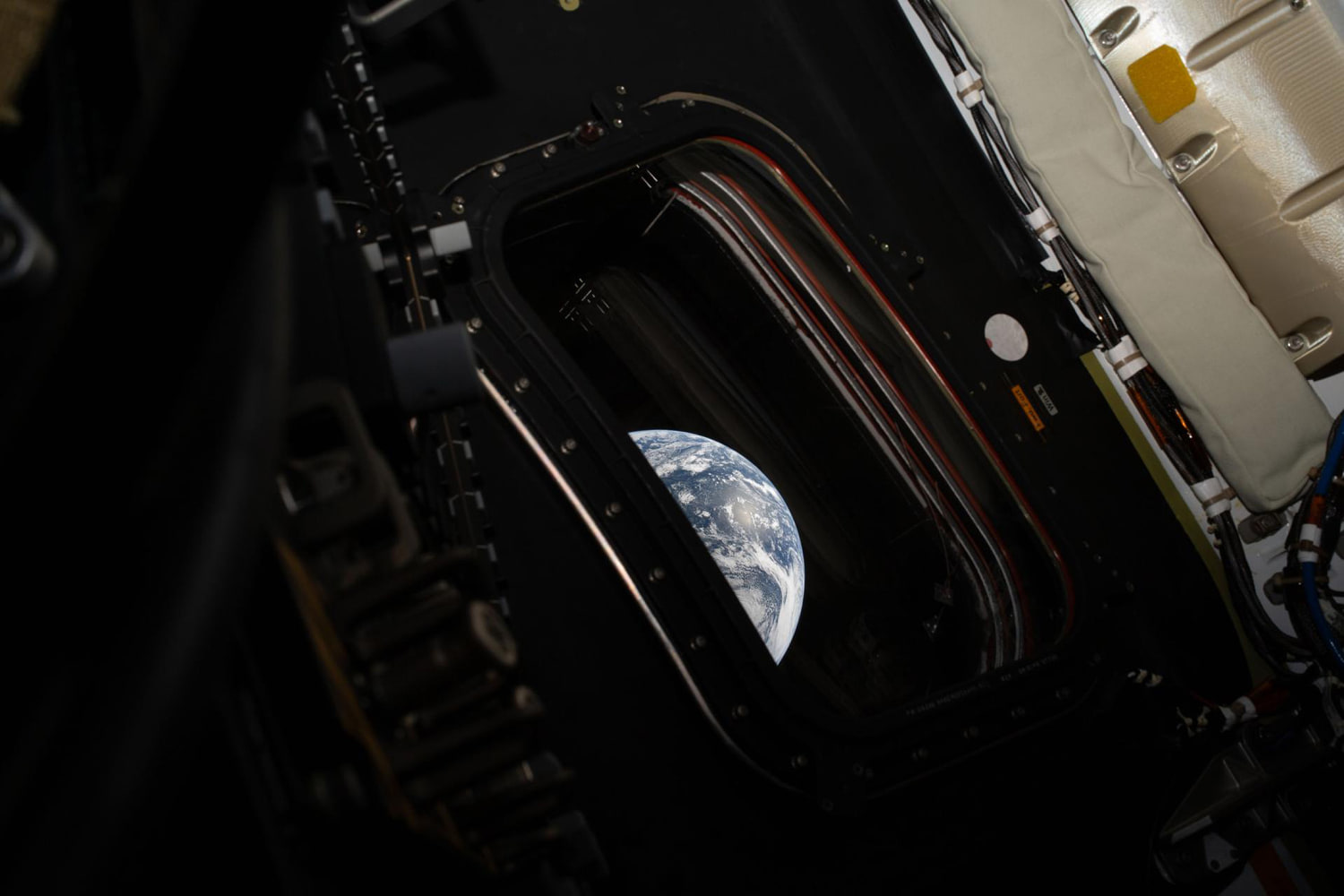
The Artemis II mission profile deviates from standard Low Earth Orbit (LEO) missions by utilizing a High Earth Orbit to test life support systems before committing to a lunar trajectory. This specific positioning—reaching an apogee of approximately 74,020 kilometers—provides a unique vantage point for terrestrial imaging. At this distance, the Earth subtends an angle significant enough to allow for wide-field sensor calibration.
The optics used to capture these images are integrated into the spacecraft’s situational awareness suite. These sensors must maintain thermal stability despite the extreme temperature gradients of space. When the Orion spacecraft captures the Earth from this distance, it is testing the solar array wing cameras and the internal handheld high-resolution hardware. The primary technical constraint is the bandwidth required to transmit high-definition data back to the Deep Space Network (DSN).
Three Structural Components of Optical Validation
The utility of these images can be categorized into three distinct operational pillars:
Navigational Reference and Star Tracker Alignment
Optical navigation (OpNav) relies on the ability of the onboard software to distinguish between planetary bodies and background star fields. By capturing Earth at varying distances, engineers verify that the software correctly identifies the planetary limb—the edge of the atmosphere against the vacuum of space. This data point is essential for autonomous return-to-Earth sequences if ground communication is lost.Thermal and Structural Integrity Monitoring
The cameras used for Earth imagery are often mounted on the Solar Array Wings (SAWs). These cameras monitor the deployment and structural health of the arrays. The Earth serves as a high-contrast backdrop that allows ground controllers to detect micro-vibrations or debris impact damage that might be invisible against the blackness of space.Radiation Shielding and Sensor Degradation Analysis
High Earth Orbit exposes the hardware to the Van Allen radiation belts. High-resolution imagery provides a metric for "noise" in the CMOS sensors. Over time, radiation causes "hot pixels" or sensor degradation. Analyzing the clarity of Earth images allows mission control to quantify the impact of radiation on the spacecraft’s optical hardware in real-time.
Communication Bottlenecks in Deep Space Telemetry
The transmission of high-resolution imagery creates a significant load on the S-band and Ka-band communication links. Artemis II utilizes the O2O (Orion Artemis II Optical Communications System) laser terminal, which aims to increase data rates from standard radio frequency limits to 260 Mbps.
The "cost" of an image in space is measured in bits per second versus power consumption. A single high-definition frame must compete for bandwidth with critical telemetry data, such as oxygen partial pressure, battery voltage, and crew biometric stats. The prioritization of imagery occurs only during periods of high-link availability. This creates a staggered data release schedule where "low-res" thumbnails arrive first for immediate engineering verification, followed by "lossless" RAW files for scientific and public distribution.
The Earth as a Calibration Target
Earth is not merely a subject; it is a known quantity used to calibrate the spacecraft’s multispectral sensors. Because the spectral signature of Earth is well-documented by LEO satellites like Landsat, the Artemis II team uses these images to "tune" the sensors for the Lunar environment.
The Albedo Effect—the amount of sunlight reflected by a planet—varies significantly between Earth and the Moon. Earth’s high albedo (approx. 0.30) provides a bright light source to test the dynamic range of the cameras. This ensures that when the spacecraft reaches the Moon—a much darker body with an albedo of approx. 0.12—the sensors are adjusted to prevent underexposure or loss of detail in the lunar shadows.
Human Centricity and the Psychological Buffer
Beyond the mechanical, there is a functional requirement for imagery in crewed missions that does not exist in robotic probes. The view of Earth provides a critical psychological "anchor" for the four-person crew. In long-duration spaceflight, the "Overview Effect" is a documented cognitive shift, but from a strategy perspective, it serves as a high-value tool for crew morale and mental performance.
The ability of the crew to manually capture images using handheld cameras provides a layer of redundancy. If the external automated cameras fail, the crew must be capable of documenting the spacecraft's exterior and Earth's position for backup navigation. This manual task-loading is part of the mission's "human-in-the-loop" testing phase.
Limitations of Current Imaging Technology
While the imagery is advanced, it is limited by the physics of the Orion’s orbital velocity. Motion blur and shutter speed must be precisely managed, especially during the perigee swing-by where the spacecraft's relative velocity to the Earth's surface is highest.
Furthermore, the lighting geometry—the angle between the Sun, Earth, and Orion—determines the "phase" of the Earth seen in the images. Most public-facing images are selected for their "Full Earth" or "Crescent Earth" aesthetic, but for engineers, the most valuable images are those taken at high phase angles (backlit), which reveal the composition of the Earth's atmosphere and any potential outgassing from the spacecraft.
Strategic Transition to Lunar Vicinity
As Artemis II moves away from Earth, the focus shifts from Terrestrial Imagery to Lunar Proximity Operations. The data gathered during the Earth-viewing phase dictates the exposure settings and compression algorithms used for the remainder of the mission.
The objective is to establish a "Library of Optics" that future Artemis missions (III through V) will use as a baseline. If the Artemis II images show a specific type of sensor flare or chromatic aberration when pointed toward a bright light source, the software filters for the Lunar Gateway can be patched before the first components are launched.
The operational success of Artemis II hinges on the transition from "Earth-reliant" to "Earth-independent" systems. The final images of Earth captured before the lunar flyby represent the last data points for ground-truthed calibration. Once the spacecraft passes behind the Moon, it enters a period of communication silence where it must rely entirely on the autonomous systems validated by those initial Earth-facing observations.
Engineers will now pivot to analyzing the thermal impact of the Earth-rise transition, where the spacecraft moves from the Moon's shadow into direct sunlight. The contrast ratios recorded in the Earth images will define the safety margins for the lunar landing sensors in subsequent missions. The mission's next phase involves the execution of the return trajectory, where the Earth images will no longer be used for calibration, but as the primary target for re-entry alignment.